Powered trailer project
2016 Jan 28th
The idea for this trailer came from a need to pick up and deliver bikes and scooters for my e-bike business without using a car. This is especially important here on Salt Spring Island, as going off island means getting on a ferry, which costs $$$. By using the BC Ferries "Discover" card bikes travel free, even when they are 19 feet long!
So here's the plan:
1. 8 foot long cargo bed capable of carrying three bikes, or two bikes in boxes.
2. Welded steel frame for strength and ease of fabrication.
3. Two medium power direct drive hub motors in 20" rims with matching controllers capable of regen braking.
4. On board battery capable of powering the two controllers.
5. Reasonably nice looking as it will be going to events etc.
I took a look on line, especially at Tony's Trailers, as he makes large steel bike trailers. The most important take away was how he drops the cargo bed below the level of the axles. This keeps the load low for stability. I have tipped my kiddie trailer on at least one occasion, resulting in a laptop falling out, and going skidding across the road.
I thought about using round tubes like Tony's Trailers, but ended up going with square tubing to simplify joints. The base frame is made from two bed frames that I picked up from the buy and sell. The uprights and rails are 0.75" and 1.0" square 0.063 and .0065" wall, hot rolled steel tubing. The tongue is 1" X 2" 0.083 wall tubing.
Welding was fairly straight forward, I am not a great welder, it just takes persistence sometimes. It is quite easy to blow through the 0.063 wall tubing, but the holes can be welded over. I thought about a fold down tail gate, but ended up just using a tube that attaches with large plastic thumb screws that thread into nuts welded to the bottom of the tube.
I also put one of these adjacent to the wheels ,between the upper rails. It is handy to secure bikes to, and reinforces the trailer structurally as well.
The most critical part of the welding was to make sure the axles were perfectly aligned, so that there would be no extra drag or tire wear. A piece of angle iron run across all four drop outs worked for this. Clamp the drop outs in place, tack them on, re check the alignment, then weld.
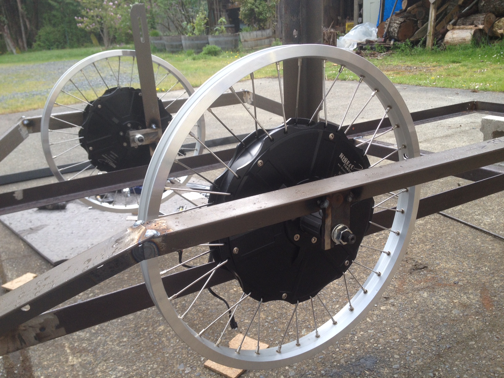
The motors are the new Nine Continent M3007RC. They are direct drive hub motors with built in cassette freewheels, instead of the usual threaded freewheel attachment. These are special order, and can be laced into a variety of rims from 20" to 700C. They are suited to power in the 500-1200 watt range. Please contact me to order.
I wanted to be able to adjust the power levels, and things like when the motors start relative to the towing bikes motor, so having a Cycle Analyst V3 made sense. So the throttle signal on the towing bike is split off between the throttle and CA on the towing bike, as well as the ebrake signal. I also wired up a three way switch on the towing bike for power limiting the trailer. The signal wires as well as a 14 gauge ground wire terminate in a quick disconnect at the trailer hitch. The heavy ground wire ties the negative of the two batteries, on the bike and the trailer together, so that the the throttle and other signals have a common reference.
The Grinfinion 25 amp controllers are mounted on a plastic project box that contains all of the connections. A Grin shunt-CA3 connects between the battery and the controllers to get the current consumption from both controllers. There is also a DC to DC converter, a flasher circuit for the rear lights and a switch that toggles between flash and steady.
I used a hub motor type water proof connector that has three larger, and five smaller connections. This has proven to be not 100% reliable, and a pain to take apart, so I bought this one from Digikey, switchcraft 6282-6PG-3DC and 8282-6SG-3DC I will replace the original Ebay item with these eventually.
I cut off all of the JST plugs on the CA3 and Shunt, and used a couple European style barrier strips to connect everything. This turned out to be a mistake. These strips accept only bare wires, and they have been the source of some trouble, as it is easy to make a less that reliable connection, especially when inserting two or three small wires in one hole. I plan to change these to Cinch Jones style terminal blocks, and crimp ring terminals to the wires.
For the trailer hitch I found this nice 12mm quick release ball joint on Ebay from this store http://stores.ebay.ca/illstonandrobsonltd/
I welded up a clamp that attaches to the seat post of the towing bike, and bolted the ball to that.
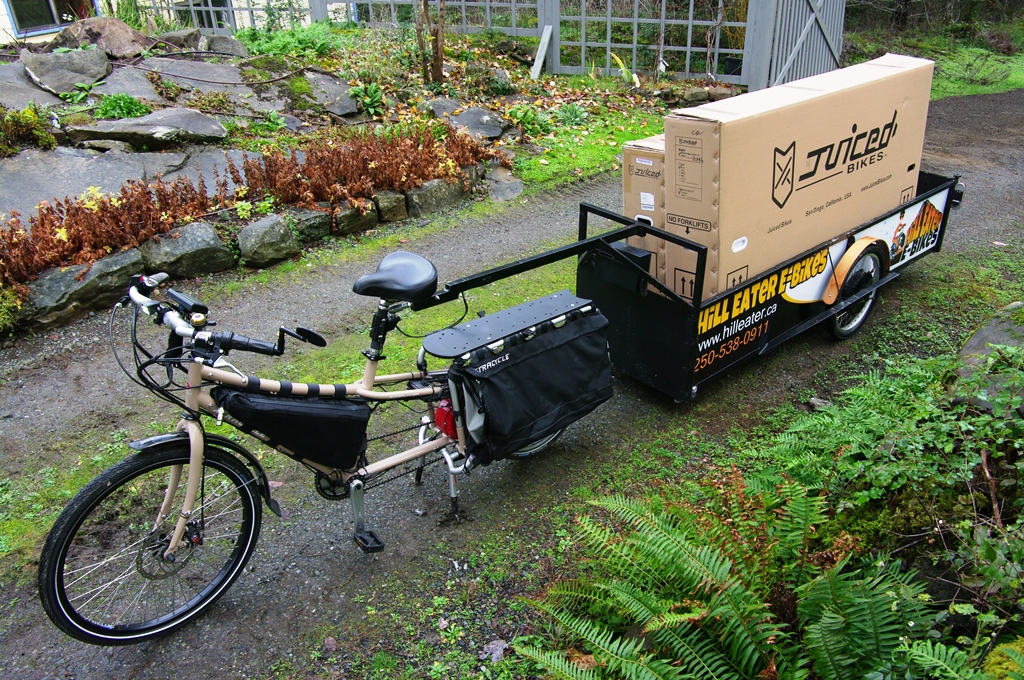
- My Edgerunner Stoked. Note the Expedition battery 48V, 20 AH battery and bag, if you are in Canada, and interested in a battery like this please get in touch. The Stokemonkey kit is available as a special order item, as are Edgerunner acessories.
I considered doing a 5th wheel type arrangement and bolting the ball to the cargo rack on the Edgerunner. But I think the seat post is more versatile, it could be switched to another bike, even a non powered bike if you added a throttle and ebrake. The loaded trailer is heavy, so the location of the hitch is important. If it were at the axle or behind the back tire then the weight of the trailer may tend to try to kick the back of the bike out sideways if you brake or apply power while turning. As it is now if you apply power in a corner the push from the trailer wants to push the bike over, so you have to lean into the corner harder. This is something that you can adjust to.
The motors are the new Nine Continent M3007RC hubs in 20" wheels. Looking at the Grin motor simulator I chose a winding that would top out at about 35 km/h at 52 volts. This is a good speed for long distance towing, I would not want to go much faster. Towing this rig with a couple hundred pounds on board feels like driving a freight train. There is plenty of power on tap, I actually dialed the max power back from 50 amps to 38, the full power is simply not needed. The last trip I made it used 19 Wh/km which would give me a max range of about 50 km with the Prius plug-in battery.
The battery I got as an experiment from Hybrid Auto Center. This was before I started selling the Expedition batteries. Something like a 25ah 52 volt Samsung 25R pack would have been smaller and lighter. Anyways, the Prius pack is 20AH, 52 volts in a 14S 1P configuration.
It should be capable of 200 amps, and it should last a long time. Problem is that it is big and heavy at 16 pounds. The cells are metal can Panasonic lithium with handy screw terminals on the top.
- batt 4.JPG (152.28 KiB) Viewed 396 times
The pack is held together in compression with riveted metal straps, and has plastic spacers with provision for air cooling between the cells.
Hybrid Auto Center does not seem to be carrying them any more. I wanted to be able to set a lower balance point, like 4.05 volts, to extend the battery life, so I picked up a Founding Power programmable BMS. This turned out to be a pain in the ass, as programming involves interfacing to a PC and running their programming software, which is not all that intuitive.
Two other problems with this BMS, it can't take a turn on surge, it goes into alarm if you try to turn it on with the controllers connected, so I had to put in a soft start button that charges the controllers caps through a resistor. The other problem is that it takes its power from the first few cells, so if you leave it on for a few weeks it unbalances the cells. A cheaper standard 14S BMS would probably have been fine, maybe with the addition of some connectors to plug in a Cell Log once in a while to check the cell balance.
I built a battery box from 1/8" marine plywood, with two layers laminated with epoxy. its not to easy to work with the thin plywood, but with this laminating method I could make a water tight lid that fits on nicely. I secured the lid with bungee straps.
The fenders were also made with the same method, bending two layers of thinner plywood strips over a C shaped plywood form, gluing and clamping.
The bed is 1/2" okume plywood, which I routed out in a square grid pattern on the bottom side to take some weight off. This was a lot of work, but the material seemed just too heavy. I finished it with three coats of spar varnish. I also installed a couple of light aluminum channels that bike tires can sit in. I had these sitting around. Another option would be to purchase a car carrier bike rack that holds multiple bikes on the roof or a pickup bed, and bolt this into the trailer.
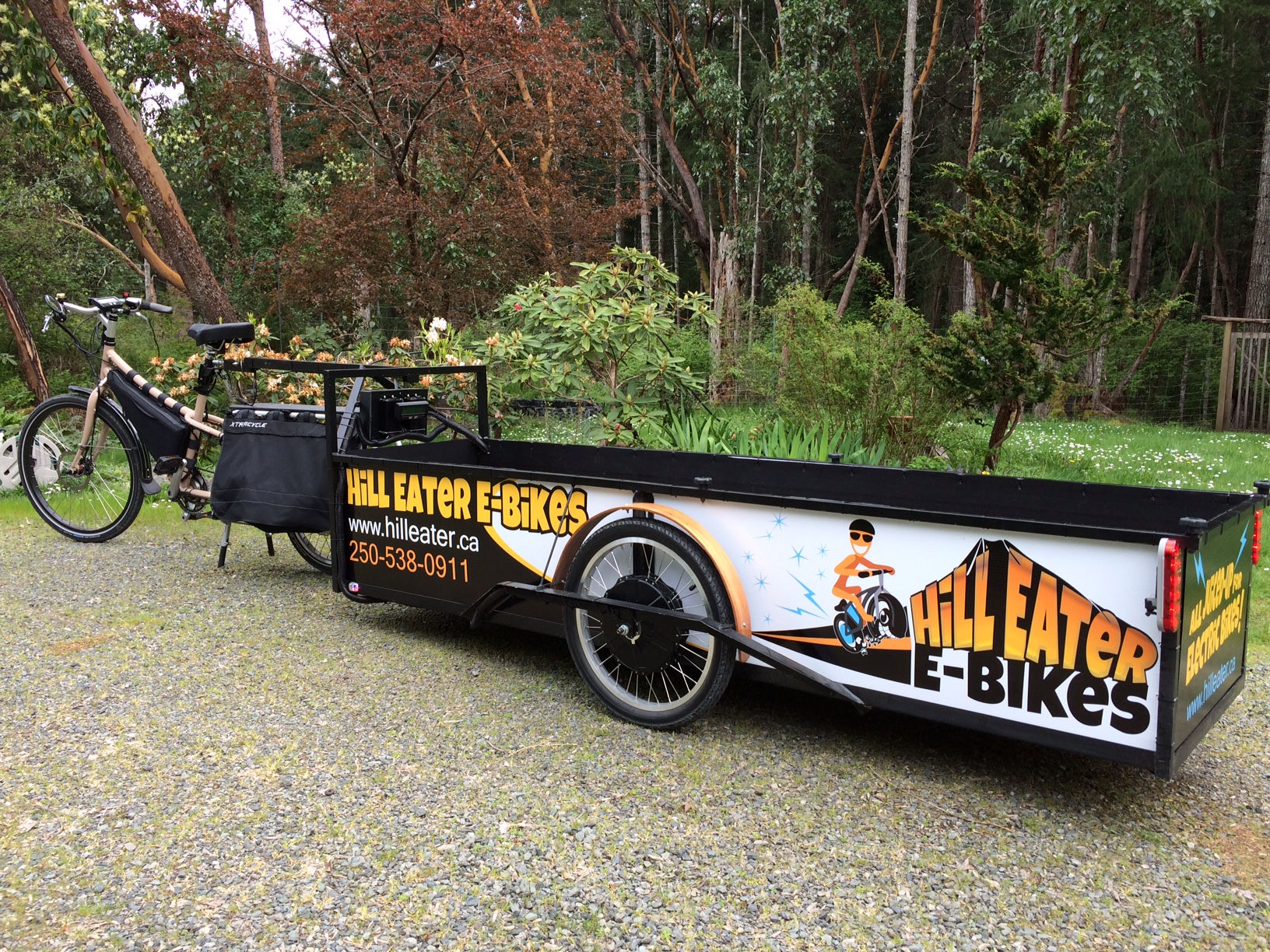
Further plans include making up coroplast side panels with my logo printed for advertising.
The biggest shortcoming of the trailer is the lack of a suspension. I thought of a way to do this, with a pivot point ahead of each wheel, and a bike shock behind the wheel. Maybe I will get around to doing the modification eventually.
Another improvement would be to use moped type rims for a heavier duty wheel. The bike rims I used are holding up fine so far.
- 165 pound scooter
Carrying 20 foot pipe sections, a compressor and tools
Waiting for the ferry with a full load of Expedition batteries
The trailer works as expected, and it is surprisingly powerful. If I stop on a hill with it loaded up, I can hardly move the bike and trailer, yet with a touch of the throttle, up it goes, no problem at all. The variable regen also works well, it really is essential for safety.